Our Business

Guide for Technical Documents

HOME Our Business S-Mark Types and Procedures Guide for Technical Documents

  • · Illustration of Preparation of the Cover
    · Enter *Notes 1, 2, 3 and 4 on the side (edge area) as well.
    1. Note 1. If there are several TCFs (i.e., in case there are 3 TCFs), mark like "1/3. 2/3. 3/3"
    2. Note 2. Enter product name, type and model name in the bracket below TCF.
    3. Note 3. Enter day, month and year of submission.
    4. Note 4. Enter name of business.
    · Illustration for preparation of table of contents
    · Instructions at the time of preparation
    1. Note 1. 「Check list on technical capability and production system assessment」 shall be prepared in case of product assessment by each type only, which is not applicable when certification has been applied in individual product.
    2. Note 2. Please mark N/A (Not Applicable) at the corresponding list if there are no corresponding issues among the above table of contents. Example) In case the product applied for certification is an electrical part, 3. Fluid, gas relevant drawings (N/A)
  • Method to prepare technical documents

    · Prepare list of drawings

    · Illustration of preparation
    No. Name Drawing No. Volume Remarks
    1 Overall Assembly Drawing KOSHA-01 1
    2 Appearance Assembly Drawing KOSHA-001 1
    3 UP/DOWN UNIT KOSHA-002 1
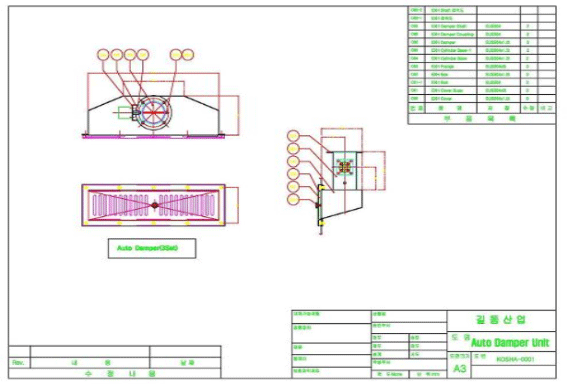
    4 AUTO DAMPER UNIT KOSHA-0001 2
    5

    · Prepare drawings to enable understanding the structure of the equipment

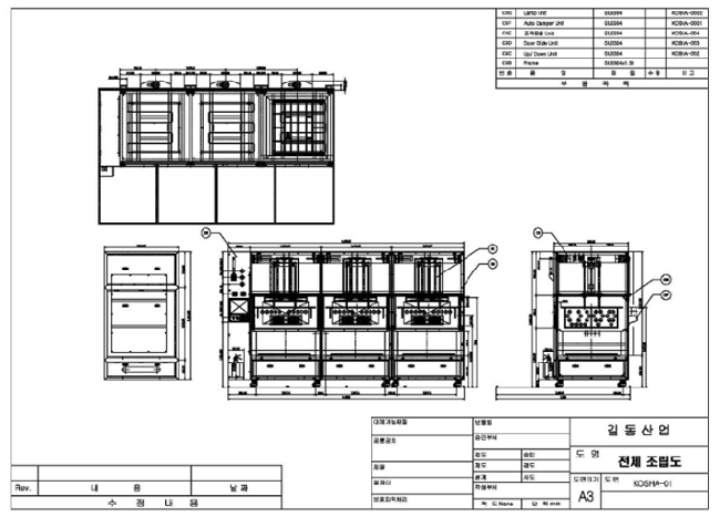
    · Overall Assembly Drawing and Partial Assembly Drawing
    1. Note 1. Enter names of the major structural parts in the overall assembly drawing in order to understand all.
    2. Note 2. If structure of the equipment cannot be understood from the overall assembly drawing, prepare a partial assembly drawing where the major structural parts by each part are entered in.
    · Illustration of an Overall Assembly Drawing
    전체조립도
    · Overall Assembly Drawing and Partial Assembly Drawing
    전체조립도

    Prepare drawings concerning safety and protective system.

    Note 1. Layout of Protective System
    1. Products subject to the obligatory safety certification under the Law on Industrial Safety and Health such as; safety device of press and shearing machine, overload prevention device of crane, safety valve of pressure container, pressure restrictive switch of boiler, emergency stop device of elevator, protective cover of grinding machine and safety mat of industrial robot, etc. should receive the obligatory safety certification, and the detailed drawing submitted at the time of obligatory safety certification shall be attached.
    2. Drawings specifying the type of the protective device and location of installation shall be submitted. Example) Photoelectric type safety device (Approach Sensor), two-hand control safety device, safety valve of pressurized container, etc.
    Note 2. Risky driving (structure) part
    1. Drawings of the parts where risk is existent due to fall of strength by concentration of load or stress shall be submitted. Example) Power transmission shaft, structures under load, rope and chain, etc.
    Note 3. Drawings shall be prepared to show installation of cover on driving part, safety distance of photoelectric type safety device and safety gap to prevent constriction, etc., and the sizes should be entered in.
    Note 4. Drawings specifying materials of piping, packing and sealing, etc., aside from tank, shall be submitted if harmful substances like chemicals are applied or stored.
    List of drawings shall be prepared.

    Refer to illustration of preparation of drawing list of machinery·apparatus

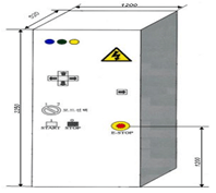
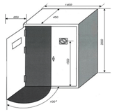
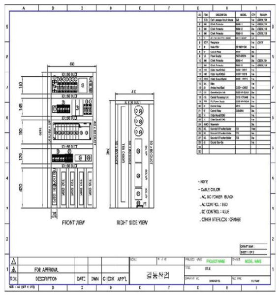
    Prepare appearance diagrams of the control box.

    Appearance diagrams specifying appearance size and location of power switch, control button and lamp, etc., shall be prepared.

    Prepare layout of the internal electrical/electronic parts and attach specification list of the parts.

    Clearly specify capacity, quantity, model No. and manufacturer in the specification of the parts.

    Prepare a power and control circuit diagram, ground and emergency stop circuit diagram and interlock circuit diagram, etc.
    Prepare an interlock list.

    Symbols, names, roles, scope of blockage and method of blockage in use shall be entered in.

    · Illustration of Interlock List.
    Order Symbol(Note) Name Role Scope of Blockage Method of Blockage
    1 EMO Emergency Stop S/W Disconnects power to the equipment in the time of emergency Main power cut Hard-wire and PLC
    2 L1 Inspection Door S/W Disconnects power to the driving part at the time of opening/closing door at the inspection area Power cut to X, Y Axis Motor Hard-wire and PLC
    ---The rest is omitted---
    Note. Enter the same symbol in use at the electrical circuit diagram in the sympol column.
    · Illustration of preparation of appearance diagram of the control box
    Instructions

    Instructions

    1. Enter the external sizes.
    2. Display all parts attached at the appearance like control button and lamps, etc.
    Instructions

    Instructions

    1. Location of the main power circuit breaker and the emergency stop switch is suitable at 0.6m~1.9m, but 1.7m is recommended.
    2. Angle of door opening shall be more than 95°, and 0.9m is desirable for span of the door.
    · Illustration of preparation of internal electric/ electronic parts layout and specification of the parts
    Illustration of preparation of internal electric/ electronic parts layout and specification of the parts
    Instructions at the time of preparation
    1. Include manufacturer, model name of the internal electric/electronic parts and whether they are certified or not, when preparing.
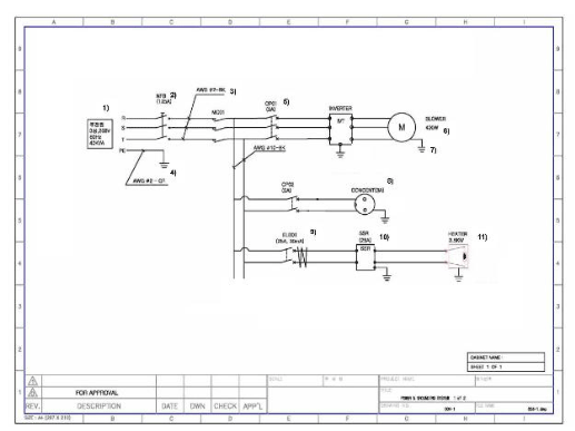
    · Illustration of preparation of power circuit diagram
    Illustration of preparation of power circuit diagram
    Major issues to be entered at the time of preparation
    1. Note 1. Enter specification of power of the main power (Input power).
    2. Note 2. Enter capacity on the circuit breakers like wiring circuit breaker, etc
    3. Note 3. Enter specification of wiring of the power line.
    4. Note 4. Enter specification of wiring of ground wire.
    5. Note 5. Enter the rated capacity at the over-current protective device.
    6. Note 6. Enter the rated load capacity at each load.
    7. Note 7. Mark ground at each load.
    8. Note 8. Enter the rated capacity at consents.
    9. Note 9. In case of the earth leakage breaker, enter the rated sensitivity current, etc.
    10. Note10. Enter contact capacity of SSR(Solid state relay).
    11. Note11. In case of a heater, enter the rated capacity and mark grounding.
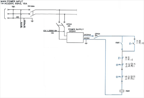
    · Control Circuit Diagram (Sequence Diagram)
    Control Circuit Diagram (Sequence Diagram)
    Instructions at the time of preparation
    1. Control circuit shall be supplied with power through primary and secondary insulated/ isolated transformer, and the primary and secondary insulated/ isolated transformer should supply power through the mounted DC power supplier even though DC has been applied as the control circuit power.
    2. Overcurrent protective device should be applied at one terminal of the secondary part of control circuit transformer, while ground should be applied at the other terminal, and the circuit should be formed to have no contacts between the control coil and the contact.

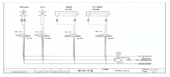
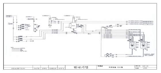
    · Prepare circuit diagram and P&ID (or piping diagram)

    · Illustration of a Circuit Diagram
    Illustration of a Circuit Diagram
    Instructions at the time of preparation
    1. Note 1. Enter type and quantity of the substances to be applied.
    2. Note 2. Enter material and size of the piping.
    3. Note 3. Parts requiring setting on the diagram (pressure switch, pressure controller, etc.) shall enter the set points.
    4. Note 4. In case of the solenoid valves, input/output relationship should be entered clearly.
    · Illustration of P&ID
    Illustration of P&ID
    Prepare a local exhaust ventilation diagram.
    1. Example 1) Shape and size of hood and duct(Attach design calculation data).
    2. Example 2) Types of exhaust substances, flow velocity of exhaust, flux of exhaust, exhaust pressure, etc.
  • · Manual for Safety Marks

    User Manual, Safety Marks and Instructions should be prepared in Korean

    Please refer to "Attachment 1. Assessment criteria on the user manual under Safety Certification Regulation" for detailed preparation method.

    Explanation on the name plates and safety marks, etc.
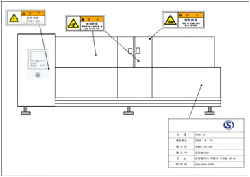
    1. Prepare kinds of name plates and instructions (contents, size), safety marks.
    2. Specify the locations of attachment of each kind of safety parts and name plates in the appearance diagram
      Illustration of displaying location of attachment of the name plates and safety marks
    Manual for Safety Marks
    · Explanation on Operation and control

    The followings are the major issues to be included in the explanation on Operation and Control

    1. Issied to be taken care of for safety
    2. Summary and major specification (Specify condition and environment to use)
    3. Names of major structural parts
    4. Explanation on major structural parts and control box
    5. Control method, etc.
    Location of attachment of the emergency stop system and the interlock switch, methods of control, release and re-start shall be described in detail.
    · Explanation on Maintenance and Inspection

    The following are major issues to be included in the maintenance explanation.

    1. Inspection intervals and list
    2. Abnormal situations and countermeasures
    3. Method to adjust and replace major parts
    4. Contents concerning treatment of harmful substances
    5. Spare parts list, etc.
    · Explanation on Transportation and Installation

    The following are major issues to be included in the explanation on transportation and installation.

    1. Instructions during transportation and installation
    2. Transportation and installation methods
      Ex.) Enter type and lifting capacity of the transportation equipment, etc.
    3. Drawing of base foundation and installation space (if applicable), etc.
  • Data on design criteria & Strength Calculation

    Prepare in consideration of ergonomical design contents.

    Ex.) Enter location, height and place of the emergency stop button, control box and touch screen.Workability, accessibility, handling of heavy loads and identifiability, etc., shall be considered.

    Prepare calculation data on safety distance when installing the photoelectronic type safety device.

    Refer to the Common Technical Standard S2-M-3-2009(3) concerning machinery and apparatus for calculation method.
    · Illustration of calculation of safety distance for the photoelectronic type safety device
    Prepare design calculation data of the local exhaust ventilation.
    1. Layout of duct (Enter specification like sizes)
    2. Material, friction loss (loss per each length of duct) and bending loss, etc. shall be considered.
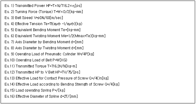
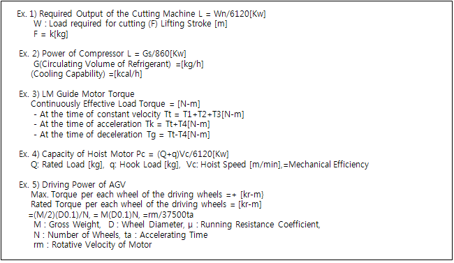
    Prepare strength calculation data on safety related risky driving (structural) part.
    1. Pressure container, structures under load, stopper, safety block, rope and chain, etc.
    · Illustration of the major formulae applicable for designing (1)
    Illustration of the major formulae applicable for designing
    · Illustration of the major Design Calculation Formula by each Equipment (2)
    Illustration of the major Design Calculation Formula by each Equipment
    Prepare selection data of the materials applied according to the harmful substances.
    1. Attach data on corrosion resistance, acid tolerance, alkali resistance and chemical resistance, etc.
    2. Selection data of the materials applied shall include data on tank, piping, packing and sealing, etc.
    3. Submit test results for the materials applied in case that the characteristics of such harmful substances are not well-known because that substance was newly developed.
    Prepare MSDS data, etc.
    1. MSDS data can be searched from MSDS unified search banner of homepage of Korea Occupational Safety & Health Agency (www.kosha.or.kr).
    2. This is applicable when harmful, hazardous substances are applied.
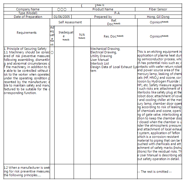
  • Checklist of applies standard(Just in case of components)

    · Illustration of the method to prepare self assessment data
    Illustration of the method to prepare self assessment data
    1. Note 1. Enter the name of technical standard of the part.
    2. Note 2. Adequate: Mark when adequate for requirements.
    3. Note 3. Inadequate: Mark when it is inadequate for requirements but the inadequate mark cannot be allowed because the final result of improvement should be adequate.
    4. Note 4. N/A: Mark when the requirements (standard) are not applicable.
    5. Note 5. Reference documents: Enter drawings, circuit diagrams, test records and user manual, etc., which are related with the requirements.
    6. Note 6. Opinion: Enter the result of assessment for the requirements at the time of designing and manufacturing.
  • Instructions at the time of Preparation

    · Attach results of test/ measurement executed by the business place itself or external recognized test organization.
    1. If certified by the external recognized certification organization, attach the test record specifying date of certification, certification No. and certifying organization, etc.
      1. Ex. 1) Mechanical field: Noise, temperature, material, leakage test, pressure-proof test ans tensile test, etc.
      2. Ex. 2) Electrical field: Insulation resistance, withstanding voltage test, earth continuity test, EMC test (if applicable), etc.
        1. In case of self test by the business place, attach inspection/ calibration record of the testing machines.
        2. Testing list can vary by each product according to safety certification criteria.
    2. Attach legally obligatory test/inspection or documented evidences of model recognition such as; test record of dangerous machinery·device and record (If applicable) on performance test (protective device, safety apparatus, etc.).

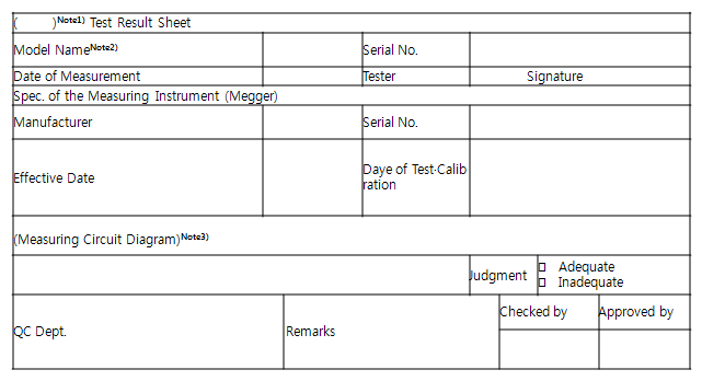
    Illustration of preparation of each kind of Test Records

    · Electrical Field
    1. A. Cover

      test result sheet
      1. Note 1. Enter type of tests like withstanding voltage and insulation resistance, etc.
      2. Note 2. Enter name of model of the product.
      3. Note 3. Draw brief circuit and enter the instrument of measuring position. However, if the circuit is complicated, attach on the back page.
    2. A-1. Test Result (Insulation Resistance)

      Insulation Resistance Test Result Sheet
      Object of Measurement Tested Spec. Test Result
      Measuring Point Data RV[V] Wire-Wire/Wire-Earth Test Voltage[V] Measured Value[MΩ] Reference Value[MΩ] Adequate/Inadequate
    3. A-2. Test Result (Withholding Voltage)

      Withholding Current Test Result Sheet
      Object of Measurement Tested Spec. Test Result
      Measuring Point Data RV[V] Wire-Wire/Wire-Earth Test Voltage[V] Measured Value[㎖] Reference Value[㎖] Adequate/Inadequate
    4. A-3. Test Result (Earth Continuity)

      Earth Continuity Test Result Sheet
      Object of Measurement Tested Spec. Test Result
      Measuring Point Data Cross-section of Earth Test Voltage[V] Test Current[A] Measured Value[Ω] Reference Value[Ω] Adequate/Inadequate
    · Mechanical Field
    1. A-4. Test Result (Noise)

      Noise Test Result Sheet
      Measuring Point Data Measuring Condition Tolerance Measured Value [DB(A)] Adequate/Inadequate
      Primary Secondary
      Front of M/C M/C Paused Shall be lower by 10dB(A) then the measured value when in 'standby'
      M/C Full Load Less than 85dB(A)
      Right of M/C M/C Paused
      M/C Full Paused Less than 85dB(A)
      Rear of M/C M/C Paused
      M/C Full Paused Less than 85dB(A)
      Left of M/C M/C Paused
      M/C Full Load Less than 85dB(A)
    2. A-5. Test Result (Temperature)

      Earth Continuity Test Result Sheet
      Order Measuring Point Data After 1 Hour(℃)Note1) After 4 Hours(℃) After 8 Hours(℃) Adequate/Inadequate
      Surrounding Temp. Measured Temp. Surrounding Temp. Measured Temp. Surrounding Temp. Measured Temp.
      Average
      Max.Value
      Note 1. Measuring time and interval shall vary according to the characteristics of the equipment.